
PCM Audio
In basic terms, a PCM audio file is a digital interpretation of an analog sound wave (1) whose goal is to replicate the properties of an analog audio signal (3) as closely as possible to the original source (4), called fidelity (2). The conversion from analog to digital PCM audio is done through a process called sampling (5). In the process of sampling, we will consider the sampling rate (7) and the bit depth (6).
First, we will define PCM audio, then we will explain how we go from analog to digital. We will also compare it with Dolby Digital and Bitstream. Let´s go.
PCM audio (Pulse Code Modulation) is a process that is utilized to convert analog audio signals that are represented by waveforms to digital audio signals which are represented by ones and zeros without neither compression nor loss of information.
This process allows the recording of sound footage, whether a musical performance or a movie soundtrack to be managed in a smaller space, virtually and physically, without losing quality.
To get a visual idea of the space taken up by analog and digital audio, compare the size of a vinyl (audio) disc to that of a CD (digital).
PCM audio streams have basic properties that determine their fidelity to the original analog signal: the sampling rate and the bit depth
- The sampling rate, that is, the number of times per second that samples are taken; and the bit depth
- Bit depth is the number of bits of information in each sample and determines the number of possible digital values that each sample can take.
PCM audio (Pulse Code Modulation) is a process that is utilized to convert analog audio signals that are represented by waveforms to digital audio signals which are represented by ones and zeros without neither compression nor loss of information
PCM audio is the audio standard for all digital consumer formats such as CDs, DVDs, Blu-Ray Discs, etc.
PCM audio streams have basic properties that determine their fidelity to the original analog signal: the sampling rate and the bit depth
The act of converting analog sound to digital sound is the foundation for digital audio. This reproduces the sound through the use of digital signals, which are much easier to work with since they can be corrected without losing quality and in fact, may sound better.
Digital audio has been a part of the music recording industry since the 1970s despite experimental recordings from the 1960s. The typical digital audio format is PCM audio or modulation of sound pulse codes.
Pulse Code Modulation (PCM audio) represents analog signals in digital format. PCM audio is the standard for audio on computers and is used in the audio CD format, too. The audio CD format is referred to as “Redbook” and is the property of Royal Philips Electronics, Inc., known simply as Philips, and must be licensed by them in order to be used. Quantified in numerical code, typically binary, the PCM audio begins as analog signals sampled for the magnitude and are then converted.
Conversion To Digital PCM audio
Converting analog to digital PCM audio can be complex, depending on the content to be converted, the desired quality you want to achieve, and how the information is to be stored, transferred, and distributed.
The conversion from analog to digital PCM audio is done through a process called sampling.
As mentioned earlier, analog sound moves in waves, while digital audio is a series of ones and zeros.
To capture analog sound using PCM audio, specific points on the sound waveform from a microphone or other analog audio source must be sampled.
The amount of the analog waveform sampled at a given point (called bits) is also part of the process. More points sampled in combination with larger sections of a sound wave sampled at each point means more accuracy revealed at the listener end.
As an example, for an audio CD, an analog waveform is sampled 44.1 thousand times per second (or 44.1kHz), with dots that are 16 bits in size (bit depth). In other words, the digital audio standard for CD audio is 44.1 kHz / 16 bits.
PCM Audio and Home Cinema
PCM audio is used in CD, DVD, Blu-ray, and other digital audio applications. When used in surround sound applications, it is often referred to as Linear PCM audio or Linear Pulse Code Modulation (LPCM).
PCM audio produces a series of numbers or digits, and hence this process is called digital. Each one of these digits, though in binary code, represents the approximate amplitude of the signal sample at that instant.
In Pulse Code Modulation, the message signal is represented by a sequence of coded pulses. This message signal is achieved by representing the signal in discrete form in both time and amplitude.
The pulse code modulation (PCM is the acronym in English of Pulse Code Modulation) is a method of modulation used to transform a signal analog into a sequence of bits ( digital signal ) method invented by British engineer Alec Reeves in 1937 and that it is the standard form of digital audio in computers, compact discs, digital telephony, and other similar applications. In a PCM stream the amplitude of an analog signal it is regularly sampled at uniform intervals, and each sample is quantized to the nearest value within a range of digital steps.
The linear pulse code modulation (LPCM by stands for Linear Pulse Code Modulation ) is a specific type of PCM audio in which digital quantization levels are linearly uniform. This contrasts with PCM audio encodings in which the quantization levels vary as a function of the amplitude of the sampled signal and the algorithms of A- law and Mu – Law . Although PCM audio is a general term, it is often used to describe linearly encoded signals as in LPCM.
PCM audio streams have basic properties that determine their fidelity to the original analog signal:
- the sampling rate, that is, the number of times per second that samples are taken; and the bit depth
- Bit depth is the number of bits of information in each sample and determines the number of possible digital values that each sample can take.
The method uses a sampling of the abscissa of the signal at regular intervals; the read values are then quantized inordinate and finally digitized (generally coded in binary form ). PCM audio is widely used in telephony systems, but many video standards, such as ITU-R BT.601, are also based on this principle. Since pure PCM audio requires a very high bitrate, consumer video standards such as DVD or DVR are based on its variants which make use of compression techniques. Very frequently, PCM audio coding is used to facilitate digital transmissions in serial form.
Is PCM Audio Better Than Dolby Digital?
PCM audio is better than Dolby Digital because whereas PCM audio is not compressed Dolby Digital is compressed. Therefore, PCM has more fidelity to the source track while Dolby Digital occupies fewer space thanks to the compression.
However, Dolby TrueHD, on the other hand, is a lossless audio format, like a zip file, which is identical to PCM audio, in theory. There are some technical differences but in terms of quality of sound and fidelity to the source, they are identical.
PCM vs Bitstream
For the setting PCM and Bitstream in different pieces of equipment, please read our article regarding PCM versus Bitstream, which one to choose, there is no direct answer that I can provide you here because this selection will depend on your requirements.
Pros And Cons Of PCM audio
Pros
The advantage of digital signal coding, as used by PCM audio, over a continuous-time signal is the higher interference tolerance. The binary coding of the receiver only has to distinguish between a high and low signal (0 and 1). The different types of modulation (except PCM audio are pulse-amplitude modulation, pulse width modulation, pulse phase modulation, pulse frequency modulation digital modulation) also have a different “resistance” against systematic or random errors. With PCM audio-modulated signals, in contrast to the other types of modulation, sinusoidal interference (for example Mains hum ) can be eliminated by regeneration amplifiers. For this reason, this method has not only become established in communications technology, but also in classic analog technology ( high fidelity ).
Cons
The disadvantage of PCM audio coding is that it is required a high data transfer rate ( approx. 1.4 Mbit /s for the audio CD ), which is why adapted and expanded PCM audio methods are used in various applications and the digital information is reduced by means of source coding.
Modulation
In the figure below, a sine wave (in red) is sampled and quantified in PCM audio. Samples are taken at regular time intervals, shown as vertical gray lines. For each sample, one of the possible values (on the “y-axis”) is chosen using a certain algorithm. This produces a completely discrete representation of the input signal (blue dots) that can be easily encoded as digital data for later storage or manipulation.
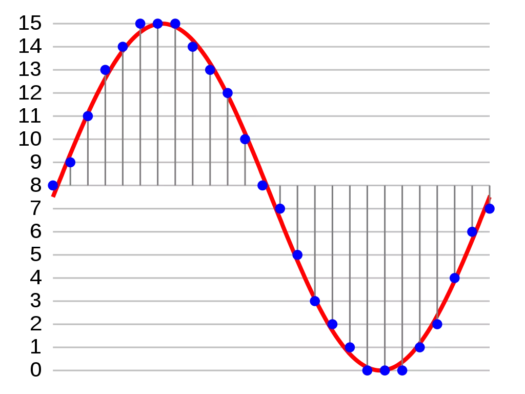
For the sine wave example, it can be verified that the quantized values at the sampling moments are 8, 9, 11, 13, 14, 15, 15, 15, 14, etc. Coding these values as binary numbers could result in the following set of nibbles or four-bit numbers: 1000, 1001, 1011, 1101, 1110, 1111, 1111, 1111, 1110, etc.
These digital values could then be processed or analyzed by an additional digital signal processor. Multiple PCM audio streams can also be multiplexed into a larger aggregated data stream, generally for transmission of multiple streams over a single physical link. A technique used for this is called time-division multiplexing (TDM) and is widely used, especially in modern public telephony systems.
The PCM audio process is commonly implemented on a single integrated circuit generally known as an analog-to-digital converter (ADC).
The figure below shows the arrangement of the elements that make up a system that uses encoded pulse modulation. For reasons of simplification, only the elements for the transmission of three channels are represented.
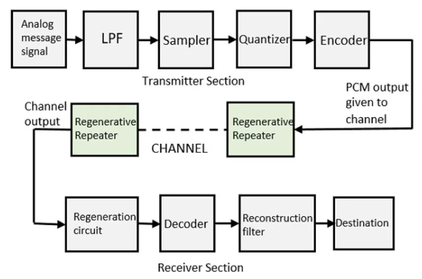
Arrangement of elements in a 3-channel PCM audio system.
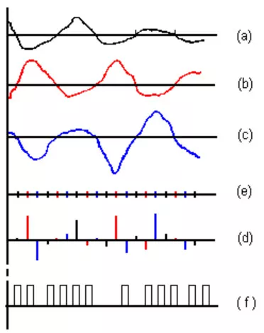
The figure below shows the waveforms at different points of the previously represented system.
The vocabulary used in the description of PCM audio varies according to the quantification techniques used. Here are some of the most common terms:
- Pulse: These are the electrical transmission pulses;
- Modulation: is the process of varying the characteristics of the signals in order to transmit the information;
- Demodulation: production of output, or data, from the modulation process;
- Sampling: reduction of a continuous signal to a discrete signal that is translated into a set of values based on a point in time.
Sampling
It is the process that consists in taking samples (measurements) of the signal value, n times per second, which represents n voltage levels in one second. For a voice telephone channel, it is sufficient to take 8,000 samples per second, that is, one sample every 125 μs, since according to the sampling theorem, when taking samples of an electrical signal with a frequency that is twice the maximum frequency of the signal, these samples will contain all the information necessary to reconstruct the original signal.
As in this case, the sampling frequency is 8 kHz, it would be possible to transmit up to 4 kHz, therefore sufficient for the voice telephone channel, where the highest frequency transmitted is 3.4 kHz.
The separation time between samples (125 μs) could be used to sample other channels using the time-division multiplexing procedure.
Quantization
It is the process by which a certain discrete value is assigned to each of the voltage levels obtained in the sampling. In the sampling of telephone conversations, as the samples can have an infinite number of values in the range of intensity of the voice, a range that in a telephone channel is approximately 60 dB. In order to simplify the process, what is done is to approximate the closest value of a series of predetermined values.
The methods for achieving PCM audio vary depending on quantization or signal processing. Quantization techniques are based on mathematical processes such as logarithmic, linear, and adaptive.
Each controls signal processing according to its own set of rules. In audio, an uncompressed process of a linear signal is used. Sample rates for audio vary for CDs and for audio programming. Higher bandwidth means higher sampling rates. Telephony has a lower bandwidth rate and uses a non-linear signal process.
Encoding
In encoding, each level of quantization is assigned a different binary code. The shape of a wave would be indicated as (f) in the third figure
In telephony, the analog voice signal with a 4 kHz bandwidth is converted into a 64 kbps digital signal, a figure obtained by multiplying the sampling frequency (2 x 4kHz) by 8 bits of each sample. To transmit multiple voice channels, the plesiochronous transmission is used, in which an additional 29 additional signals could be interleaved, if the E1 digital transmission format is used. Thus, 32 x 64 kbps = 2048 kbps are transmitted (30 channels for voice signals, one for signaling, and one for synchronization).
Demodulation
To recover the original signal from the sampled data, a “demodulator” applies the modulation procedure in reverse. After each sampling period, the demodulator reads the next value and shifts the output signal to the new value. As a result of these transitions, the signal has a significant amount of high-frequency energy caused by the Nyquist Effect.
To eliminate these unwanted frequencies and leave the original signal, the demodulator passes the signal through analog filters that suppress power outside the expected frequency range. The sampling theorem shows that PCM audio devices can operate without introducing distortions within their frequency bands if they provide a sampling frequency that is twice the input signal.
In standard systems, the quantization intervals have been chosen in such a way that this distortion is minimized as much as possible so that the recovered signals are an almost exact image of the original ones. Within the signal recovery, quantification intervals are no longer assigned but levels, equivalent to the midpoint of the quantization interval in which the normalized sample is found.
The electronic circuitry involved in producing an accurate analog signal from the discrete data is similar to that used to generate the digital signal. This circuit is called a digital-to-analog converter and is the one used by DAC devices.
Limitations Of PCM Systems
There are potential sources of deficiencies implicit in any PCM audio system:
- Choosing a discrete value that is close but not exactly at the analog signal level, for each sample, leads to quantization error.
- No signal measurement is made between samples; the sampling theorem guarantees unambiguous representation and signal recovery only if it has no energy at the frequency half the sampling frequency, known as the Nyquist frequency or higher; signals at higher frequencies are generally not represented or recovered correctly.
- Since the samples are time-dependent, a precision clock signal is required for accurate reproduction. Although the clock encoding or decoding is not stable, the variation of its frequency will directly affect the output quality of the device.
Digitization As Part Of The PCM Process
In conventional PCM audio, the analog signal can be processed (eg, by amplitude compression ) before being digitized. Once the signal is digitized, the PCM audio signal is generally subjected to additional processing (eg, digital data compression).
Some forms of PCM audio combine signal processing with encoding. Earlier versions of these systems applied processing in the analog domain as part of the analog to digital conversion process; the latest implementations do so in the digital domain. These simple techniques have been largely considered obsolete alongside modern transform-based audio compression techniques :
- The DPCM (Differential PCM) encodes the PCM audio values as the differences between the actual and predicted values of the input signal. An algorithm predicts the next sample based on the previous samples, and the encoder only stores the difference between those values. If the prediction is reasonable, fewer bits can be used to represent the same information. For audio, this type of encoding reduces the number of bits required per sample by around 25% compared to PCM.
- The ADPCM (adaptive DPCM) is a variant of DPCM that varies the size of the quantization step, to allow further reducing the bandwidth required for a given ratio of signal to noise.
- Delta modulation is a form of PCM audio that uses one bit per sample.
In telephony, a standard audio signal for a single phone call is encoded as 8,000 analog samples/sec, 8 bits each, giving a 64 kbps digital signal known as the DS0 signal. The default signal compression encoding in a DS0 signal is either Ley PCM audio (in North America and Japan) or Ley A PCM audio (In Europe and most of the rest of the world). These are logarithmic compression systems in which a number of linear 12 or 13-bit PCM audio samples are assigned a value of 8 bits. This system is described in the international standard G.711. An alternative proposal for a floating-point representation, with 5-bit mantissa and 3-bit radix, was abandoned.
Where circuit costs are high and loss of voice quality is acceptable, it sometimes makes sense to compress the voice signal even further. An ADPCM algorithm is used to map a series of 8-bit PCM audio Mu-Law or A-Law samples into a series of 4-bit ADPCM samples. In this way, the capacity of the line is doubled. The technique is detailed in the international standard G.726.
Later it was found that even further compression was possible and additional standards have been published. Some of these international standards describe systems and ideas that are covered by privately owned patents and therefore the use of these standards requires payments to patent holders.
Some ADPCM techniques are used in voice over IP communications.
Encoding For Serial Transmission
The PCM audio signals can be either return to zero (RZ) or non-return to zero (NRZ). For an NRZ system to be synchronized using in-band information, there must be no long sequences of identical symbols, such as ones or zeros. For binary PCM audio systems, the density of symbols “1” is called the density of ones.
The density of ones is often controlled using precoding techniques like Run Length Limited encoding, where the PCM audio code is expanded into a slightly longer code with a guaranteed limit on the density of ones before modulation in the channel. In other cases, additional frame bits are added to the stream, ensuring symbol transitions at least occasionally.
Another technique used to control densities is the use of a randomizing polynomial in the raw data that tends to convert its stream into a stream that looks pseudo-random, but where the raw data stream can be recovered exactly by reversing the effect. of the polynomial. In this case, long strokes of zeros or ones are still possible at the start but are considered unlikely enough that they are within normal engineering tolerance.
In other cases, the long-term direct current (DC) value of the modulated signal is important, since a DC offset tends to bias detector circuits outside its operating range. In this case, special measures are taken to keep a count of the accumulated DC displacement and modify the codes if necessary so that the DC displacement always tends to zero.
Many of these codes are bipolar codes, in which the pulses can be positive, negative, or null. In the typical alternate brand inversion code, non-zero pulses alternate between being positive and negative pulses. These rules can be violated to generate special symbols that are used for plotting or for other special purposes.
History Of PCM Audio
Let´s visit how PCM audio originated and how it has changed forever the way we exchange information and in a way, how do we communicate with the world.
In the history of electrical communications, the first reason to sample a signal was to be able to interleave samples from different telegraphic origins and send them over a single cable. The multiplexing time division (TDM) telegraphic was achieved in 1858 by the American inventor Moses Gerrish Farmer for two telegraphic signals traveling on the same pair of conductors, for which it made a patent application that was granted in 1875.
The electrical engineer Willard M. Miner, in 1903, used an electromechanical switch for time multiplexing of various telegraph signals and also applied this technology to telephony. It got intelligible conversations from channels sampled at a rate above 3500 to 4300 Hz, but the performance was unsatisfactory at less than this speed. This was TDM, but with pulse width modulation instead of PCM audio.
In 1920, the Bartlane wireline still image transmission system, named for its British inventors Harry Guy Bartholomew and Maynard Leslie Deedes McFarlane, used telegraph signaling of punched characters on paper tape to send quantized image samples in 5 levels of gray, a number that increased by 15 in 1929. The patent for this system was applied in Great Britain in 1921 and in the United States the following year and, in the latter country, it was granted in 1927.
The images that could be transmitted across the Atlantic Ocean, between the United States and the United Kingdom, In less than three hours, they were decoded at the receiver using telegraph printers that had the right typefaces.
But the first transmission of a still image that is considered digital occurred in 1957 when Russell Kirsch processed through the SEAC (Standards Eastern Automatic Computer) of the United States National Institute of Standards and Technology, an image of his son of 3 176 X 176 pixel. This technology, with its improvements, would be used by NASA in the following decade for the transmission of images used in remote sensing.
On November 30, 1926, American inventor Paul M. Rainey of Western Electric was granted the patent for a facsimile telegraph system that transmitted its signal using 5-bit PCM audio, encoded by an optomechanical analog-digital converter.
The machine did not go into mass production. British engineer Alec Reeves and French Edmond Maurice Deloraine, unaware of this previous work, conceived the use of PCM audio for voice communications in 1937 while working for the French subsidiary of the American company International Standard Electric Corporation. The patent application explained the theory and its advantages but offered no practical uses.
Reeves and Deloraine applied for a patent in France and in the United States in 1938, and the latter was granted in 1941. The first digital voice transmission made use of the SIGSALY encryption and encryption system, used for high-level communications of allied nations during World War II, in 1943. That year, Bell Labs researchers who designed SIGSALY realized that the use of PCM audio had already been proposed by Alec Reeves.
In 1949, the Ferranti-Packard Company of Canada built a radio system with PCM audio that was capable of transmitting digitized radar data over long distances for the Canadian Navy DATAR system.
The PCM audio in the 1950s used a cathode ray tube with a perforated mesh to encode. As with an oscilloscope, the beam was scanned horizontally at a given sampling rate, while vertical deflection was controlled by the analog input signal, causing the beam to pass through high or low portions of the mesh. The mesh interrupted the beam, producing binary code current variations. This mesh was perforated to produce binary signals in Gray code instead of using the natural binary system.
In addition to its use in telecommunications, the PCM audio system began to be used for music recording and production. In 1967, engineers at the NHK Technical Research Laboratory(Japan Broadcasting Corporation) developed a monaural PCM audio recorder and, two years later, had developed a two-channel PCM audio that sampled audio at 32 kHz frequency and 13-bit resolution by recording the signals on a videotape recorder helical scan.
Between 1969 and 1971, the Japanese company Denon hired an NHK stereo recorder to make experimental recordings that led to the first commercial recordings made digitally: the albums “Something” by the American jazz saxophonist Steve Marcus and “The World of Stomu Yamash’ta “by Japanese musician and composer Stomu Yamashta, both produced in 1971.
The results of these recordings led Denon to design his own PCM audio equipment based on video recorders, 8-channel audio sampled at 47.25 kHz with 13-bit resolution. Initially, they created the DN-023R model for use within their recording studios in Tokyo, and in 1977 Denon, a company from whom we have reviewed many products, developed an improved and smaller PCM audio recording system, the DN-034R, as mobile equipment which was brought to Japanese studios, France and the United States to make commercial recordings.
In the United Kingdom, the British corporation BBC also experimented with the use of PCM audio technology with the development of a 13-channel audio system, made in 1972 to improve the audio of its television broadcasts. This system continued to be used until 10 years later.
For their part, engineers from the British company, now defunct, Decca Records also developed, in the mid-1970s, digital audio recording and post-production equipment for internal use, based on the series’ video recorder. IVC800 of the American company International Video Corporation.
These systems were in use until November 1997, when Polygram Records, a buyer of Decca Records, closed the “Decca Recording Center” and sent ten of those teams to its Dutch subsidiary, to make digital transcripts of its archival material.
In the United States, the company Soundstream founded at the University of Utah in 1975 by Thomas G. Stockham, became the first in the nation to produce digital audio recordings. The recording equipment, which is considered the world’s first digital audio workstation, was developed using ADC and DAC converters, a commercial unit of magnetic tape for instrumentation from Honeywell, and a DEC computer. PDP-11/60 for storing audio. For recording, text command lines were entered into the computer.
In 1978, the 3M company entered the competition for the development of PCM audio equipment for audio recording with its 2-channel audio system, sampled at 50 kHz at 16 bits per sample. The recording was stored on a tape-recorded at 45 inches per second. The success of the 3M system led the company to produce a 32-channel audio recorder.
Soundstream closed its operations in 1983, unable to compete with the Japanese company Sony Corporation, which decreased the sampling rate to 44.1 kHz. The 3M company could not compete either, since the systems of these companies did not use, like those designed by Sony, video recorders to store digitized music, which was more practical.
In Japan, Sony developed its first digital audio processor for home use, the PCM audio-1 model, which was followed by the PCM audio-1600 model, introduced in March 1978, and using a video recorder in U-Matic format.
Today, with the introduction of computing, PCM audio recording equipment no longer uses tapes but computer hard drives to record from 1 to multiple channels, using hardware such as sound cards, high-quality microphones. and mixing consoles along with commercial or free software components for audio recording, editing, and mastering.
Further Readings
We have some other interesting articles for you to read, we have selected our top articles below, and tried to keep this list short.
We have a technical vademecum where we discuss industry terminology and how it can be useful for you. Selected examples are the definition of PCM audio, then comes the comparison between PCM and Bitstream, the comparison between DTS Neo 2.5 and Dolby Digital, and the process to match amplifiers to speakers.
Also, we have reviewed some interesting DAC: The Elgar Plus from dCS, and the Schiit stack. where the Modi 3 behaves as an entry-level DAC.
In our reviews of AV receivers, we can recommend you to read some of our favorites, the ones that we liked the most, and trying to make the list short, we have the Denon AVR-X2500H, the Onkyo TX-NR686. We also have reviewed completely the Denon 8K receivers where we have studied the 8K Denon AVR-X2700H, the Denon AVC-X6700H, the AVC-X4700H, and the AVC-X3700H.
If you are into amplifiers, my favorite is the McIntosh MA9000, and that is why I would like to recommend you to read that review. My second favorite amplifier is the Mark Levinson 5805.
Regarding speakers, we have reviewed tiny bookshelf-speaker devices to large towers. My favorites were: the Devialet Gold, the Devialet Silver, the ProAc Response DT8, the Bowers and Wilkins 805 D3,
We do not review many headphones, but if you want a Sennheiser headphone for less than 100 dollars, we have this Sennheiser HD595 review.
We have some TV and monitor reviews and here we recommend the Samsung NU8000 (for gamers!) and my favorite is the review of the classical Pioneer Kuro.
Our home theater aficionados want to know everything about video definitions and configurations. So we studied 720p, how to scale it to 1080p the right way, and compared 1080p with 1440p and demonstrated why 1440p is not always better. Likewise, we had the urge to compare 1440k with 4K and try to find out how much are we gaining with the change.

I am Bob. I work as an audio engineer and audio technician. I work in mastering and arranging bridges in existing songs and the arrangement and orchestration of the chorus. In Planet HiFi I test gear for a couple of days and write a review. I also write about AV topics, amplifiers, speakers, and headphones.
